Trapped Ion Mobility Spectrometry
Conventional drift-time (DT)-ion mobility spectrometry (IMS) separates ions based on their drift time, td, through a gas-filled tube in the presence of a constant axial electrical field. The ion drift velocity, vd, is proportional to its mobility, K, and the electric field strength, E: vd = KE. Ion separation in DT-IMS occurs on the millisecond timescale, and is generally incompatible with trapping mass analyzers, such as FTICR, or other slower analysis methods, such as electron activated dissociation (ExD) tandem MS.
Bruker Daltonics recently introduced an alternative IMS technique known as the trapped IMS, or TIMS. A TIMS device is a modified ion funnel with an axial field gradient (EFG) profile tailored to trap ions with different mobilities. In TIMS, ions are pushed forward by a carrier gas flow through the analyzer section in the presence of an axially variable, retarding electric field (Fig. 1A). An ion with a mobility of K is trapped in a region where the electric field strength is such that the ion drift velocity (KE) equals the carrier gas flow velocity, vg (Fig. 1B). Following the ion trapping event, E is gradually reduced by decreasing the analytical ramp voltage, ΔV, defined as the potential drop across the analyzer, to allow sequential elution of trapped ions with ascending mobilities. The mobility analysis duty cycle may be improved by configuring the axial EFG profile to allow simultaneous trapping of a new batch of ions in the front section of the TIMS device while mobility analysis of ions from a previous load is performed in the back section. Because the ion storage capacity of the TIMS device dictates the effective length of the trapping event, each TIMS analysis also takes place in a relatively short time (tens of milliseconds), thus TIMS is most effectively coupled to the fast TOF analyzer. The S/N ratios may be improved by summing up many TIMS-TOF mass spectra.
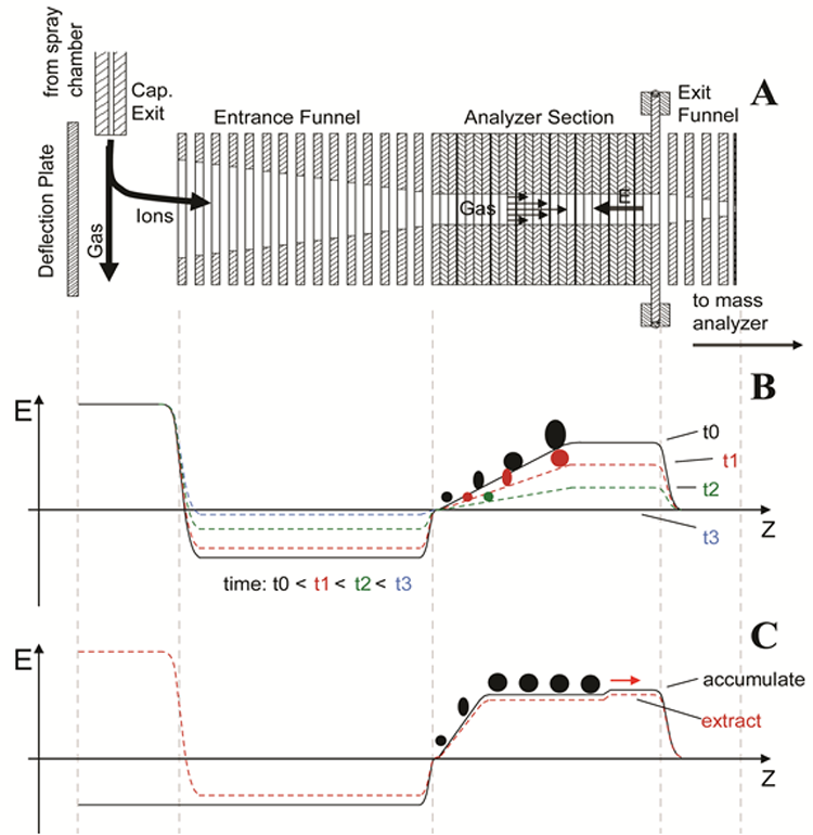
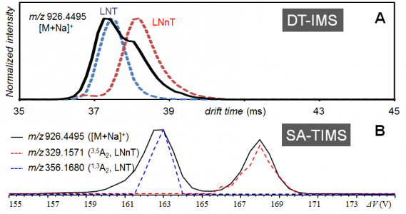
Coupling of TIMS to slower analysis methods may be achieved by re-configuring the EFG profile to allow selective trapping of ions with the desired mobility, as employed in selected accumulation (SA)-TIMS (Fig. 1C). In SA-TIMS, only ions of a single mobility may be analyzed following each trapping event. However, because ions of interest may occupy a greater volume of the mobility analyzer, a significantly longer trapping time can be used before the ion storage capacity is reached, resulting in a much higher S/N ratio per scan. The long trapping time in SA-TIMS (up to a few hundred milliseconds) allows it to be effectively coupled to slower analysis methods, including FTICR MS. The analytical potential of the SA-TIMS-FTICR MS platform was recently demonstrated for the analysis of isomeric glycan mixtures (Fig. 2).
Despite its analytical utility, prolonged ion storage in the high-pressure ion funnel region during SA-TIMS analysis can also lead to preferential ejection of ions of high m/z values due to radial ion cloud expansion and significant RF heating. An alternative approach for TIMS-FTICR coupling is to operate the TIMS analyzer in its original configuration with rapid voltage ramping and employ a gating scheme that allows passage of only ions of the desired mobility into the collision cell. Multiple collision cell fills for each ICR cell fill may be employed to improve the duty cycle. The Gated-TIMS approach has resulted in a much broader m/z operating range, and significantly reduced ion heating. Successful coupling of Gated-TIMS to FTICR MS is recently demonstrated.
Currently, we are focusing on the application of Gated-TIMS-ExD-FTICR MS/MS analysis to characterization of isomeric glycans and glycoconjugates, as well as the study of gas-phase protein conformation.
The following papers describe this research project in detail.
- Ridgeway, M. E.; Wolff, J. J.; Silveira, J. A.; Lin, C.; Costello, C. E.; Park, M. A., Gated Trapped Ion Mobility Mass Spectrometry Coupled to Fourier Transform Ion Cyclotron Resonance Mass Spectrometry, Int. J. Ion Mobil. Spectrom. 2016, 1-9.
- Pu, Y.; Ridgeway, M. E.; Glaskin, R. S.; Park, M. A.; Costello, C. E.; Lin, C. Separation and Identification of Isomeric Glycans by Selected Accumulation-Trapped Ion Mobility Spectrometry-Electron Activated Dissociation Tandem Mass Spectrometry, Anal. Chem. 2016, 88 (7), 3440-3443.