RF Oscillator
A High Voltage RF Oscillator for Driving Multipole Ion Guides
1. Abstract.
2. Advantages.
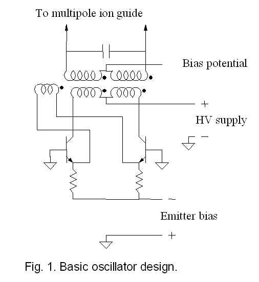
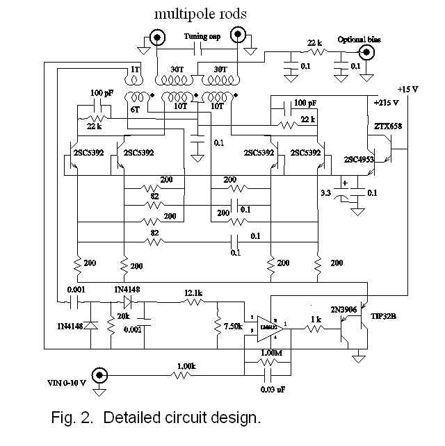
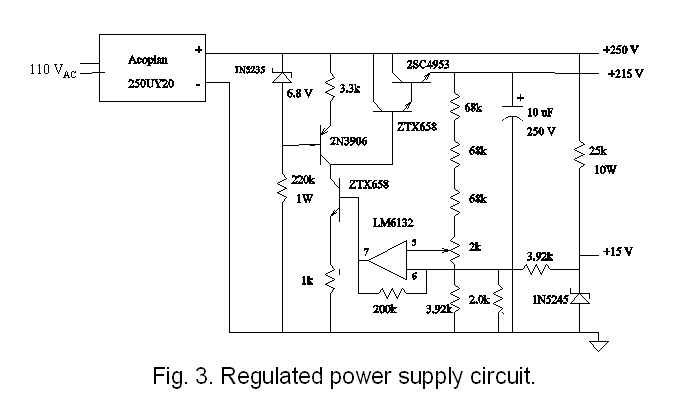
3. Circuit diagrams.
4. Citation.
5. Note: obsolete part substitute.
A high voltage RF oscillator circuit has been designed and constructed for driving multipole ion guides. The circuit is tunable from 500 kHz to 1.5 MHz by changing a capacitor and provides 0-1000 Vpp that is controlled by a 0-10 V input using a negative feedback circuit. This inexpensive circuit uses a set of high voltage transistors oscillating in tandem and does not require tuning of the resonance drive frequency as the oscillator automatically resonates at the (LC)-1/2 frequency. Matrix-Assisted Laser Desorption/Ionization – Fourier Transform Mass Spectrometry mass spectra were acquired using this tunable RF oscillator circuit to allow transmission of protein ions in the 8.5-39 kDa range through the quadrupole ion guide from the ion source to the mass analyzer.
1. It’s self tuning. No need to tune to the resonance frequency.
2. Simple control: 0-10 V input = 0-1000 Vpp output.
3. Resonance frequency is controlled by changing a capacitor.
4. It’s cheap. Should cost <$200 in parts.
O’Connor, P. B.; Earle, W. E.; Costello, C. A. A High Voltage RF Oscillator for Driving Multipole Ion Guides J. Am. Soc. Mass Spectom. 2002, 13, 1370-1375. Link
note: if you can’t download the paper, please email me and I will send you the pdf file.
As is unfortunately very common in the electronics industry, the primary transistor oscillator that is used in this circuit, the Panasonic 2SC5392 has gone obsolete. A substitute is BUH51 from ON Semiconductor, we have tested this replacement and fabricated PCBs for the RF oscillator circuit.
To download the PCB layout files with the bill of material for the RF oscillator click here.